A short update on what’s been going on
Monday, 16 March 2020

Sunday, 1 December 2019
Windscreen
Windscreen
A lot of thought and permutations have gone into the design of the windscreen frame. Design was starting to get out of control with too many complicated curves, eventually I had to get a grip of myself and simplify it 😂
I have decided to use a combination of 18mm plywood and red pine. Mainly because that’s the materials I have at hand. As you all know by now, to build one of these is bloody expensive 😂 so you need to use what you’ve got.
I am going to bend a length of 20mm tube and attach this to the back side of the plywood hoop, it will also be attached to the side panels all the way down to the deck.
After a lot of time on youtube researching what to use for the screen I have settled on 3mm Acrylic. I’ve hade a bit of practice with the heat gun and the drilling machine and believe I can do this without too much fuss 😉
The way I’ve designed the screen, I think the curves are quite slow so I’m not expecting too much stress on the Acrylic sheet.
I’m going to go for a fully enclosed cockpit.
Carving the propeller
Uh 18 propeller
Building the prop for my uh 18.
I was lucky enough to be able to borrow the prop from team hover members Chris and Ollie’s hoverwing ( their craft is almost ready) timing was good and I got a loan of it for a couple of weeks to take some measurements from and carve my own 😊
Firstly I made a router copier, using a frame I had from an old treadmill. I have to say, with all the cutting and grinding discs I used it wasn’t worth the bother using second hand material, I’d have been better off buying new steel and starting from scratch.
Anyway I made up the copier and it works a treat 😊 I set about trying to find a suitable lump of wood to practice on, timber merchants round these parts are not helpful, they don’t seem to able to think beyond stock levels on their computers 😂 I purchased a sleeper to practice on - wrong 😳 this was green timber, treated and soaking wet, not good.
Eventually I was able to purchase some suitable planks, I laminated them using epoxy resin and made up some clamps from 10mm screwed rod and 40x 20 box section. Again, like the copier, this worked a treat.
I waited two days before nervously removing the clamps ... success! - everything held nicely.
Next job was to make the jig to take the template prop and the blank.
My first attempt at carving the prop wasn’t good and had to chuck that one away. I realised that I needed to take measurements from the original prop and mark out grid references on the blank, then to make some saw cuts along the lines I had drawn for reference.
A hammer and chisel was then used to rough out the basic shape, then to finish it off with the carver copier. I have to say I was fairly chuffed with the result.
Next I used a belt sander, an orbital sander, a sanding block and a fair amount of patience 😂
Finally a spray with some guide coat and a last rub down with the machine and the prop is done. All it needs now is to be glassed and balanced.
Thrust duct continued
The thrust duct continued
With the underside of the hull complete and the skirt on, the hover has been lifted off the trestles and is now sitting in pride of place in the centre of the workshop floor.
At last the thrust duct is in place 😊 I hooked the duct up to the hoist, manoeuvred it into position and spent a lot of time making sure it was level in every direction, and I mean a lot of time 😂 I had to get this right. It’s beginning to look like a hovercraft now and not an ironing board 😂
It took me a little time to work out where the flat spot was to be cut, then the penny dropped (clang) 😂😂
So that’s it glued and set in place, it still needs to be glassed to the hull.
It’s November here in Scotland and there’s a hard frost, I have five electric heaters in the workshop and can only get the temperature up to 12 degrees c today, so definitely no glueing happening anytime soon.
Uh 18 hoverwing skirt
The skirt
I’ve been making up the hover skirt, once you get into it, it’s not so complicated. I found the trickiest bit was to get it to hang right. So I’ll tell you how I have done mine.
When I first put mine on it was terrible, sagging in places and too tight in others.
So what I did was sit the hover on trestles so it’s a good couple of feet off the ground, then start at the back of the craft by marking the centre of the skirt fabric top and bottom, use these marks to line up with the centre line on the hull top side and underside to help get it hanging right, connect up the inner and outer rear and the rear corners.
Next use drawing pins and pin the outer skirt to the outer attachment full length rear to front.
Next crawl underneath and start pinning it up on the inner attachment, working from the rear to the front. That way you can keep an eye on the bag remaining even all the way to the front - it should resemble a U shape. However as you approach the front of the craft about a foot or so before the lift duct, the skirt will begin to bunch up in places, apparently this is ok, you just add in an extra screw where needed. Just make sure you maintain an even U shape the whole way. been making up the hover skirt, once you get into it, it’s not so complicated. I found the trickiest bit was to get it to hang right. So I’ll tell you how I have done mine.
When I first put mine on it was terrible, sagging in places and too tight in others.
So what I did was sit the hover on trestles so it’s a good couple of feet off the ground, then start at the back of the craft by marking the centre of the skirt fabric top and bottom, use these marks to line up with the centre line on the hull top side and underside to help get it hanging right, connect up the inner and outer rear and the rear corners.
Next use drawing pins and pin the outer skirt to the outer attachment full length rear to front.
Next crawl underneath and start pinning it up on the inner attachment, working from the rear to the front. That way you can keep an eye on the bag remaining even all the way to the front - it should resemble a U shape. However as you approach the front of the craft about a foot or so before the lift duct, the skirt will begin to bunch up in places, apparently this is ok, you just add in an extra screw where needed. Just make sure you maintain an even U shape the whole way.


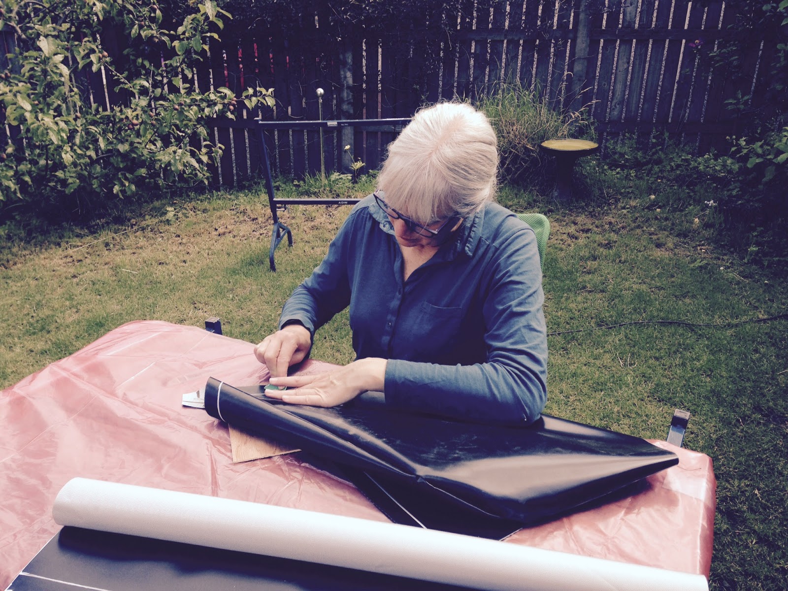 |
| Dynamite daisy preparing the vynil for glue |


Sunday, 7 October 2018
Uh18 hull vacuum bagging
The hull
We have finally reached the stage of building the hull.
I have built a table the same size as the Hoverwing to build it on so it is at a good working height. Experience over the years has taught me to make things simple and comfortable to work on; it makes life so much easier.
The foam sheets were laid out on the table and marked out according to the drawings, however I have opted to take 3 inches / 75mm off each side thus reducing the width of the craft by 6 inches. There are three reasons for doing this , the first is because the door width of my workshop is 8ft and this would make it difficult to get the craft out through the door. The second reason is there’s no need to build such a big trailer, the third reason is because I can.
After marking out the foam sheets I then made up stringer guides for marking out the shape of the hull. This worked out perfectly, I then drew round the stringers with a marker pen giving me lines to work to when it came to glueing the foam together.
I have opted for using the epoxy method and vacuum bagging, I note that other builders have on occasion gone for gorilla glue and have found it to be a powerful expanding glue that is perhaps wrong for this stage of the build and ended up having to use many heavy weights to hold it down. As it turns out vacuum bagging isn’t that difficult to do.
We made up a vacuum pump using an old vacuum pump from a refrigerator. First thing to do is identify that the pump actually works, then step two is to identify which pipe sucks in as that’s the one you want. We added in a distributor vacuum from an old MG car, these vacuums can be found very cheaply, and a micro switch so we were able to calibrate the pump to switch off at 144lbs. We also added in a one way check valve so that the bag would maintain the pressure until the pump kicked in again.
We did this by making up a trial bag for practice.
4 screws in each top sheet to stop them from moving inside the bag during the vacuum process, polythene sheet down and blankets to cover the vacuum pipe, bag sealed with duct tape, pump on and the job’s a good one.
Sunday, 8 April 2018
Trimwing and stabiliser
Trim wing stabiliser
We decided to go off plan with the trim wing and stabiliser, having previously built one following the Uh plan for another craft we found that whenever we handled the foam it would get bruised easily and leave dimples, which needed a lot of work to repair them. So by going off plan and building a wing that is more like an aircraft wing it would be lighter and stronger.
Thanks to Team hover members Chris and Oliver for doing the design.
I have built another bench 8ftx3ft in the workshop for this job
I had templates for the ribs laser cut in aluminium to help me get as an exact size and measurement as possible.
Once the ribs had been cut out with the hot wire cutter , they were set out on the bench.
I have made my wing 7ft long and not 8ft as stated on the Uh drawing , the reason for this is because the doors on my workshop are 8ft wide therefore I would not be able to get an 8ft wing through an 8ft door 😂
I don’t think this will make much difference to the handling of the craft.
I dragged the duct over to the bench and centred it with the centre rib on the bench, this method helped me to confirm that I had the boom ribs/ stabilisers in the correct place.
Although this would seem to be a lot of work and effort I think it will be worth it.
Sunday, 2 October 2016
Saturday, 20 August 2016

Saturday, 16 January 2016
Thrust duct foam layout
Duct construction
method
(Note this is a 2-man
job)
I have started to build the thrust duct and have written out a guide on how I have done it.
Many other hovercrafts have done this job before me, and this is how i have done mine. please bear in mind that this is only a guide and should you choose to do yours in the same way that is your decision and yours alone. i claim no responsibility for your efforts.
thanks for looking and good luck with your build.
1. Make two 1530mm disks from 12mm plywood using a
router. The measurement from the centre of the disk to the outside edge (that
is, the radius) should be 765mm.
 |
| first forming disc |
2. After cutting the disks, drill a 35mm hole in the
centre of each disk. Then mount them both onto a 35mm shaft.
3. Support the disks and shaft on a frame. The frame
should hold the disks so that the centre of the disks is at least 900mm from
the ground. This will allow the disks to rotate on the frame while you wrap the
plywood around the forming disks (see no.4).
 |
| mounted to frame |
4. Cut ten 2”x4”x6” blocks. These blocks will be used to
hold the disks apart. Screw each block
in place, using 2 screws in each end of each block.
 |
| block of wood to hold discs apart |
5. At this point you could tape some strong fine nylon
string around the edges of the forming disks. This could be helpful when it
comes to removing the formers from the completed duct.
6. Cross-cut 4 pieces of 3mm X 300mm plywood. Join
together to get the 4,852mm length needed. Use 6 oz plain weave glassfiber cloth
on topside and underside of each of the three joins.
 |
| cross cut plywood |
7. Sand and feather the forward edge of the 3mm plywood
to start the inlet lip radius. Mark out a centreline along the full length of
the ply and a line approximately 63mm in from each edge, these lines will help
to keep the whole thing even when wrapping around the former.
1. Pin down one end of the plywood. The two outer
guidelines should line up with the outside edge of the forming disks. Then tighten
in place around the forming disks using a ratchet strap. When you are happy
that everything is centred and tight all the way around the forming discs it is
time to nail the plywood down along the outer edges and end, glue the open ends
together. Use as few pins as possible to make removing the disks easier.
Top tip: It can be a
good idea to give the plywood a coat of resin to seal it first as the resin
will be absorbed by the plywood.
Next to cut out the foam for the outside of the duct
 |
| pined down |


9. My sheets are 600mm X 25100mm. First place a sheet on
the table and centre it. I screwed blocks to the table to hold the sheet in
place like a jig, now your jig is set to take the next sheet and so on. (Every
sheet should now be exactly the same cut.)
 |
| 50mm foam |
 |
| blocks to hold in place |
10. I marked out my sheets by making a compass 4m 40mm
long

 |
11. Drill a hole at the top end of your compass and a
second hole 457mm from the centre of the first hole. Locate your felt pen at
the centre of the top edge of the sheet and begin to move the compass from left
to right; do the same for the second hole. You should now have an arc shape,
the two parallel lines will be 457mm apart.


12. Now measure in from the end of the sheet 152mm to the
top line and 280mm from the end of the sheet to the bottom line.
13. Measure between the two parallel lines at these two
points to confirm that you have 457 between them and draw a line from top to
bottom to join these lines together.

 |
| perfect arc shape |
14. Now you should have the perfect shape for your first
segment. Repeat this process for the next two sheets. (Note although you have cut 3
sheets you will use only about half of the third sheet.) The overall
length of the outside radius should be 543.4cm.
15. Lay the segments down on a flat surface and butt join
together using 75mm screws, screwed in from the edge to the next sheet. I used
one screw per sheet per side.
 |
| butt join |

 |
| 75mm screws |
16. You need to leave a 25mm margin along the forward edge
as this needs to be kept free of cloth and resin. Mark a line 25mm in from the
leading edge then apply masking tape along this line.
Top tip: before working
with the glassfiber cloth, clean the bench and the foam sheet of all dust and
grime as this could become trapped between the cloth and foam sheet
 |
| applying masking tape |
17. When you’re happy that this is correct, fiberglass the
top side using 6oz plain weave glassfibre cloth. Only fiberglass from the
trailing edge towards the forward leading edge.
 |
| glass finer cloth |
 |
| glass finer cloth |
 |
| glass finer cloth |
 |
| epoxy resine |
 |
| epoxy resine |
 |
| top side coated with resign and cloth |
18. Immediately after epoxying the cloth to the sheet it is advisable
to remove the masking tape. Remove tape by pulling it away in a forwards
direction away from the cloth. It may be necessary to check that the leading
edge of the cloth has not lifted after removing the masking tape.
19. Flip the foam over and measure 230mm from the trailing
edge towards the leading edge. Draw a line the full length of the foam. And
another line 100mm from the leading edge.
 |
| line 230mm and 100mm |
20. Then draw another line from the point where you marked
the 230mm down the edge of the foam to 5mm.

21. When this has been done, it is now time to cut the
foam along the line between the line and the trailing edge. Use masking tape along
the top line as a guide. Masking tape can also be used along the full length of
the 5mm line.


 |
| flat sanding the wedge shape after hot wire cutting |
22. Now you should have a length of foam that resembles a
wedge shape with a flat sloped surface of 230mm. The wedged surface should be
sanded as flat as possible.
23. Using a hand saw cut slots across the width of the
foam, being careful not to go all the way through. Use 12mm plywood or make a
jig to stop the saw from cutting all the way through. The saw cuts should be
25mm apart. Do this along the full length of the foam as this should make the
foam easier to wrap around the duct.
Top tip: Practice wrapping
the foam around the duct before glueing.
24. Now, if you are confident, it is time to glue the foam
to the former using the epoxy resin. Make
sure you have an assistant; this is not a one-man job.
25. Use ratchet straps to hold the foam in place, the
trailing edge will need to be clamped, (clothes pegs can be used to do this).
26. It may be necessary to add filler pieces of foam to
the leading edge.
27. Sand the inlet radius as shown in the drawing and
fiberglass with the 6 oz cloth overlapping the plywood by about 25mm.
28. Sand and fill any low spots using epoxy filler. Do not
use anything other than epoxy based products as anything else will react with
the foam.
29. Paint epoxied surfaces a light colour to protect from
sunlight.
Subscribe to:
Posts (Atom)